Electrical symbols electronic symbols. To build a circuit you need a different diagram showing the layout of the parts on stripboard or printed circuit board.
 Wiring Diagram Symbols Wiring Diagram Priv
 The actual layout of the components is usually quite different from the circuit diagram.

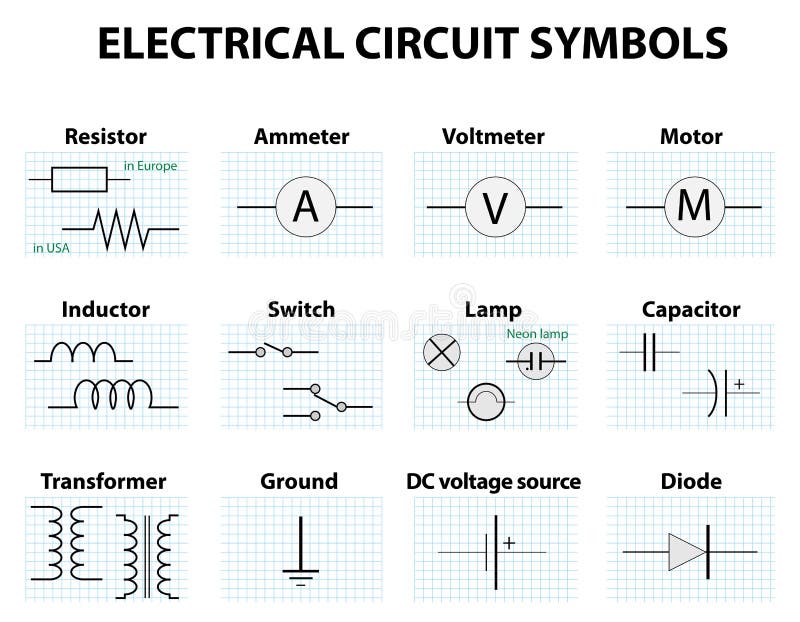
Electrical circuit diagram symbols list. Electrical symbols and electronic circuit symbols are used for drawing schematic diagram. Electrical symbols are used to represent various electrical and electronic devices in a schematic diagram of an electrical or electronic circuit. Basics 9 416 kv pump schematic.
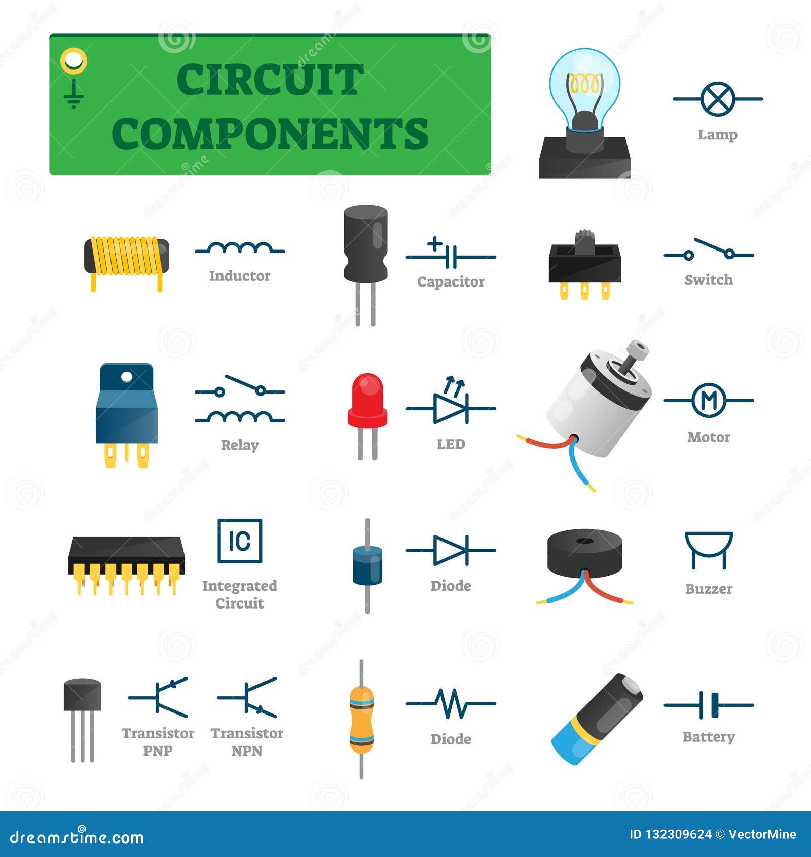
A circuit diagram electrical diagram elementary diagram electronic schematic is a graphical representation of an electrical circuita pictorial circuit diagram uses simple images of components while a schematic diagram shows the components and interconnections of the circuit using standardized symbolic representations. Reading schematics is all about recognizing the symbols and lines to see how they are connected. The presentation of the interconnections between circuit components in.
Basics 11 mov schematic with block included. There are some standard symbols to represent the components in a circuits. An electronic symbol is a pictogram used to represent various electrical and electronic devices or functions such as wires batteries resistors and transistors in a schematic diagram of an electrical or electronic circuitthese symbols are largely standardized internationally today but may vary from country to country or engineering discipline based on traditional conventions.
Most of the electrical symbols can be changed in their appearance styles and colors according to users requirements. Typical electrical drawing symbols and conventions. Electrical symbols or electronic circuits are virtually represented by circuit diagrams.
Drawing electrical circuit diagrams you will need to represent various electrical and electronic devices such as batteries wires resistors and transistors as pictograms called electrical symbols. Circuit diagrams circuit symbols are used in circuit diagrams which show how a circuit is connected together. Traditionally these symbols may vary from country to country but today they are standardized.
6 starting circuit breaker 7 rate of change relay 8 control power disconnecting device. Basics 10 480 v pump schematic. This physics video tutorial explains how to read a schematic diagram by knowing what each electric symbol represent in a typical electrical circuit.
The symbols represent electrical and electronic components. It covers circuit symbols such as resistors. Basics 8 aov elementary block diagram.
There are many electrical and electronic schematic symbols are used to signify basic electronic or. This article gives some of the frequently used symbols for drawing the circuits. Therefore to be able to read electrical schematics you need to know electrical schematic symbols and which wires connect to which component and how each line flow in an electrical schematic.
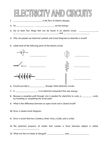
 Ps 6 8 Electricity Worksheet For Review
  Circuit Diagram Wikipedia
  Electronic Symbol Wikipedia
  Circuit Board Schematic Diagram Symbols Wiring Diagram Sys
  List Of Electrical Symbol Schematic Diagram In Drawing Chart
  How To Read An Electrical Diagram Lesson 1
  Circuit Components Vector Illustration List With Isolated
  8 Best List Of Electrical Symbols Images Electrical
  Common Circuit Diagram Symbols Us Symbols Wiring Schematic